Six Secrets for Accurate Static Pressure Testing
When static pressure testing is practiced in the field, it becomes the “go-to” test for every savvy service tech, installer, and salesperson. This five-minute test quickly assesses the operating airflow of a system and how well the distribution system is performing. Let’s take a look at typical and fairly natural mistakes that must be avoided when testing.
Once you’re aware of these testing faults, you can be certain your readings are accurate. You can also be confident in your airflow and distribution system diagnosis.
Use the Right Instruments and Accessories
Commercial testing can have a range of 0 to 10”, although a 0” to 5” scale will do for most systems. You’ll want a minimum accuracy of ±3% with a minimum resolution of .01” water column. Larger scale manometers lack the accuracy you need.
Be sure the manometer has at least two pressure ports, one positive and one negative. Also, be sure the gauge reads in “Inches of Water Column”, the prescribed unit of pressure measurement for the HVAC industry.
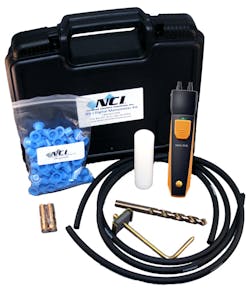
PHOTO ABOVE: An accurate manometer is one of the core instruments of a good air diagnostic technician. Pictured here is a typical static pressure testing kit (this one is wireless) that NCI recommends.
Essential accessories allow test port installation to gain access to pressure inside the equipment or ducts. These include a 3/8” drill bit and drill bit sheath. The sheath covers the bit, exposing only the last ½” of it. This prevents the drill bit from being pulled into the unseen coil or circuit board behind the test port. This avoids that nasty hissing sound which is guaranteed to give you a bad day as you nick the coil. You’ll also need test port plugs (3/8” in diameter) to seal the ports when testing is complete.
In addition, you’ll need tubing that attaches snugly to the manometer ports and a static pressure tip. These transport pressure from inside the distribution system to the manometer. (This tip is different from a pitot tube, it is smaller and has no hole in the end of the tip, just on the side of the tip. The old standby is a Dwyer A-303)
One last thing about manometers: when using analog manometers, make sure it is level when testing. The screw in the face of the manometer is to zero the gauge in the position you’re using each time you test.
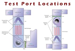
Test Port Locations
To gain access to pressure in the ducts, test ports are installed in locations that meet the intention of each pressure test. A test port in the wrong location delivers a pressure reading that tells the wrong story. This leads to system performance misdiagnosis.
Test port location will vary depending on system configuration. Here’s a general overview of each test location.
Total External Static Pressure (TESP) – Install test ports where air enters and exits the air-moving equipment. In most split systems, this is after the air filter and before the external coil. Add these two pressures together to find TESP. Compare this pressure to the equipment nameplate maximum-rated TESP.

PHOTO ABOVE: The most difficult part of learning to measure static pressure is knowing where to drill the test holes in the system to be sure you get accurate readings. These diagrams show typical test port locations on a residential HVAC System. Graphics copyright National Comfort Institute, Inc., © June 28, 2011, Cleveland, OH
Coil Pressure Drop – Install test ports before air enters the coil and exits the coil. The difference between these two measured pressures is found by subtracting them. Compare this number to the manufacturer’s published pressure drops. Be sure to verify if the coil was rated wet or dry.
Filter Pressure Drop – Install test ports before air enters and exits the filter. As with coil pressure drop, the difference between these two measured pressures is found by subtracting them. Compare this pressure to the manufacturer’s published filter pressure drops. Remember, filter pressure ratings are always for a clean filter.
Supply Duct Pressure – This is a single pressure measurement, using the coil exiting test port. Read and record the pressure. If this pressure exceeds more than 20% of fan rated pressure, odds are the duct is undersized or poorly installed.
Return Duct Pressure – This is also a single point pressure reading. You can use the test port before the filter (If the filter is located at the air moving equipment) to gather this pressure measurement. Ideally, this pressure should not exceed 20% of fan rated pressure.
Isolate any fitting, transition, or other system component – As with coil and filter pressure drop, install test ports before and after any fitting or section of the duct system and measure pressure drop over that portion of the system. This allows you to see the amount of airflow resistance for any part of the system and diagnose its performance.
Assure Fan Speed is Performing at Design Airflow
Or, it should at least perform as close as you can get to design. When airflow is less than design, each pressure reading decreases significantly. As airflow increases over design, the pressure drop of that component increases rapidly.
Your ability to interpret pressure readings is always depends on airflow through the system. Use the measured total external static pressure and fan speed setting to plot fan airflow.
Fan Rotation Direction
If your numbers look goofy, this is a hint your fan may be running backwards. This happens in commercial systems when the leads of a three-phase electrical motor are mis-wired. But it can also happen on residential fans.
Verify rotation direction by killing power to the fan, allowing it to stop then watch the direction the blades spin as the fan is started. Keep a safe distance!
Kinked Pressure Tubing
One of my most repeated mistakes is getting kinks in the tubing or I’ll stand on it. This happens because I carry long pressure tubing in my static pressure kits.
When readings are super low, check your tubing to be sure it is unobstructed and allowing pressure to travel freely through the system to the manometer.
Static Pressure Tip Facing into Airflow
When measuring system pressures, the static pressure tip reads most accurately when facing directly into airflow. The purpose of this tip is to break up the added pressure of air movement and allow a direct reading of static pressure.
This detail is more important when air velocity is higher. But when testing, flip your tip in the opposite direction after reading correctly just to see for yourself how the pressure reading changes under different conditions. This is how you learn every time you test.
Best of luck with your future pressure testing. These tests are a primary tool for every real diagnostician in this industry.
Rob “Doc” Falke serves the industry as president of National Comfort Institute -- an HVAC-based training company and membership organization. If you're an HVAC contractor or technician interested in a free report with illustrations showing how to measure static pressures, contact Doc at [email protected] or call him at 800-633-7058. Go to NCI’s website at nationalcomfortinstitute.com for free information, articles, and downloads.
About the Author
Rob 'Doc' Falke
President
Rob “Doc” Falke serves the industry as president of National Comfort Institute an HVAC-based training company and membership organization. If you're an HVAC contractor or technician interested in a building pressure measurement procedure, contact Doc at [email protected] or call him at 800-633-7058. Go to NCI’s website at NationalComfortInstitute.com for free information, articles and downloads.