
For many years some professional HVAC businesses have believed that residential HVAC equipment selection was performed following guidance in ACCA Manual J. For example, a home with a 30,000 Btu/h cooling load would use a 2.5 ton air conditioner, right?
WRONG!!
Manual J is only used to calculate the heating and cooling loads. The current, nationally-recognized Manual J8 guides HVAC system designers to use ACCA Manual S Residential Equipment Selection to select equipment that is the right size (see section 10-4).
Why use Manual S
There are three good reasons to use Manual S: It is the nationally-recognized standard, it prevents problems associated with equipment over and under sizing, and it's a requirement in the 2009 International Residential Code (IRC).
Manual S, Residential Equipment Selection, is the ANSI-recognized, national standard providing clear instruction for interpreting and applying original equipment manufacturers' (OEM) expanded performance data. Manual S instructs designers how to select equipment which meets the application requirements (heating, sensible cooling, and latent cooling) at the design conditions that were used for calculating the loads.
Manual S also sets equipment sizing limits, as summarized in Table 1. These sizing limits ensure equipment capacities will keep customers comfortable while preventing the problems associated with equipment over and under sizing which include: health issues associated with excessive humidity, callbacks from comfort complaints, higher building costs (larger equipment is more expensive, more materials are needed, and more labor is used to install it), larger energy consumption, and greater wear and tear on the equipment1.
Finally, Manual S is a code requirement. A modification adopted in the 2009 IRC clarifies an existing requirement for sizing HVAC equipment (change is underlined).
"Heating and cooling equipment shall be sized in accordance with ACCA Manual S based on building loads calculated in accordance with ACCAManual J or other approved heating and cooling calculation methodologies."
How to Apply Manual S: Heating Example (Part I)
Manual J heating load calculations produce values, in Btu/h, for selecting the heating equipment. This heating example will select a furnace for a home that has a heating requirement of 56,000 Btu/h. The furnace needed must have the capacity to deliver 56,000 Btu/h in order to maintain 70°F in the home when the outdoor temperature dips to the outdoor design temperature (refer to Section 3-6 and Table 1A of Manual J8).
Based on the home's load and the sizing limitations from Table 1, the furnace must produce more than 56,000 Btu/h, but less than 78,400 Btu/h. The home's heating capacity requirement is 56,000 Btu/h and the furnace can have a capacity no larger than 140% of the heating load (140% x 56,000 = 78,400 Btu/h).
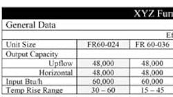
Using the manufacturer's product data (as typified in Figure 1), the XYZ model FR 80-036 or FR80-024 has the output capacity of 64,000 Btu/h, which is enough to meet the requirement. The FR 60-036 has too little capacity (48,000 Btu/h, 86% of the load), and the FR 125-036 has too much output capacity (100,000 Btu/h, 178% of the load), selecting either the FR 60-036 or the 125-036 would cause comfort complaints or lead to a more expensive system.
If you are installing this furnace at elevations above 2,500 feet there are additional requirements that must be considered, see Manual S for more information.
How to Apply Manual S: Cooling Example
Load calculations produce cooling capacity requirements for selecting the HVAC equipment. For this cooling example, we will select an air conditioner for a home with the following Manual J cooling loads:
Sensible Cooling 22,000 Btu/h
Latent Cooling 8,000 Btu/h
Total Cooling 30,000 Btu/h
| Sensible and Latent Loads The sensible load is the heat that is measured by a thermometer or a thermostat. It is heat that you consciously feel. It is the heat you associate with a desert or a dry heat. Latent load is the heat associated with airborne moisture (produces relative humidity as measured by a hygrometer or humidistat). During the cooling process, moisture is extracted from indoor air. High latent heat or high relative humidity feels humid, clammy, or steamy. An example is a home that shows a cool temperature on the thermostat but, because of high humidity, still feels uncomfortable. When you walk into this home your initial impression is that it is cool, but then as your body adjusts to the room temperature, you begin to feel sticky, clammy, and uncomfortable. You may even feel warm again. This is why two homes that have the same reading on a thermometer or thermostat can feel very different. |
Manual S has four steps for selecting cooling equipment:
1. Set the design parameters
2. Estimate the target airflow
3. Search for equipment candidates
4. Evaluate and select the acceptable candidates (more than one candidate may be offered to the customer)
Step 1. Design Parameters
There are many design parameters to consider. Some of these parameters were decided during the system design procedure: Equipment type, location, fuel, etc. However, the design parameters considered now come from the load calculations, Manual S, and the OEM performance data.
Two of the design parameters listed in Figure 3: Cooling Design Parameters relate to the design conditions used to calculate the cooling load. Unlike heating equipment, the cooling equipment capacity varies with the outdoor conditions. The outdoor (and indoor) design conditions that were used to calculate the cooling load must be used when selecting the equipment. In this case the indoor conditions were a 63°F wet bulb temperature (this is equivalent to 75°F dry bulb, 50%Rh), and an outdoor design temperature of 95°F.
Another design parameter is the sizing limit Manual S sets for air conditioners. Based on the home's load and sizing limitations from Table 1, an air conditioner must meet the total cooling load requirement (30,000 Btu/h), but can have no more than 34,500 Btu/h (115% x 30,000 = 34,500). Therefore, the air conditioner we need must produce more than 30,000 Btu/h, but less than 34,500 Btu/h.
Step 2. Estimate the Target Airflow
Target airflow for the cooling system must be estimated. Manual S provides instructions2 to use the home's sensible heat ratio (SHR) to calculate the target airflow. This target airflow narrows the search for equipment candidates. The home's SHR also indicates whether the air conditioner will need exceptional moisture removal (humid climates) or extra temperature control (hot and dry climates). This airflow rate is only a target; the actual airflow will be based on the OEM expanded performance data.
Based on the SHR of the home, our target airflow is 952CFM.
| Determining Target Airflow
Where:
|
Therefore, the cooling design parameters for the sample house are:
Step 3. Search for Equipment Candidates
The third step in the cooling equipment selection process is to search for candidate equipment combinations. However, the HVAC designer should always select a MATCHED system, a system that is rated by AHRI or certified by the OEM to deliver the specified capacity under the design conditions. Diligent HVAC system designers should examine different product lines and equipment styles when searching for equipment candidates. In addition to package and split systems, there are other low capacity heating and cooling systems which will serve small loads (e.g., ductless mini-split systems, radiant panels, and packaged terminal air conditioners).
| OEM Performance Data vs. AHRI Data AHRI produces the standards for rating various heating and cooling equipment. Manufacturers are responsible for testing and certifying the performance of their heating and cooling equipment to these standards. After equipment is tested in accordance with the appropriate standard, the OEM data is published in AHRI product directories. However, the certification and efficiency data that appears in the product directories should not be used to select the heating and cooling equipment. The test conditions AHRI uses simulate a very small geographic area in the US which restricts the use of this data. Hence, OEM expanded performance data should be used to select the properly sized equipment, and AHRI directories should only be used to compare relative equipment efficiency ratings. |
Different OEMs will present their performance data in various formats. However, each format will generally include the same basic information: required airflow through the coil, entering air wet-bulb temperature4, outdoor temperature, and the equipment's cooling capacities (usually total and sensible capacities). Based on a cooling requirement of 30,000 Btu/h is a 2.5 ton system the proper unit to select?
The 2.5 ton system (See Figure 4 XYZ Model AC 030 Performance Data) does not have enough total cooling capacity at a 95°F outdoor temperature and entering wet bulb temperature of 63°F. Therefore, choosing this air conditioner would fail to keep the customer comfortable during hot summer afternoons. In a home with a cooling load of 30,000 Btu/h, a 2.5 ton unit seems like the natural choice. However, after examining the OEM expanded performance data (with reference to the design parameters), it is apparent that this 2.5 ton system would be a poor choice.
Given the stated design parameters, the 3.0 ton system (See Figure 4 XYZ Model AC036 Performance Data) is actually a better fit. It has enough total cooling capacity (31,510 Btu/h) without exceeding the 115% limit (34,500 Btu/h). The system's sensible cooling capacity (23,000 Btu/h) also meets the sensible cooling load (22,000 Btu/h). The latent capacity (8,510 Btu/h) of this system (total ¨C sensible = latent) is sufficient to provide proper dehumidification for the example home (latent load 8,000 Btu/h).
The other design element gleaned from Table 4 is the volume of air, in cubic feet per minute5 (CFM) that must flow over the indoor air conditioner coil6 to achieve the required cooling capacities. The airflow for this air conditioner (1,050 CFM) is different than the target airflow (952 CFM). Is this difference a problem? No. The goal is to find an air conditioner with the right capacity. The process to determine target airflow provided insight to the sensible and latent cooling capacity relationships that needed to be considered. 1,050 CFM will be subsequently used in the Manual D (Residential Duct Systems) duct sizing calculations7.
Manufacturers of furnaces, fan coils, and other equipment with blower assemblies create blower performance charts for the different models they produce. These charts provide the data needed to determine how much airflow a blower assembly produces at a given fan speed when pushing air against a certain amount of external static pressure (ESP). Based on the fan speed and the amount of resistance that is external to the unit8, the chart provides the volume of air the blower assembly can move9. The XYZ furnace manufacturer produced a blower performance chart (See Figure 6 Fan Performance Data) for the FR 80-036. The furnace delivers 1,050 CFM on low fan speed with an ESP of 0.65 IWC (1,070 CFM at .60 IWC ¨C interpolated to 1,050 CFM at 0.65).
Using known specifications and experience this fan should have enough capacity to accommodate the air conditioner coil, a good filter, and the resistance from a "typical" duct system. Given the fan performance of 1,200 CFM @ 0.65 IWC External Static Pressure:
Add 0.19 IWC for the air conditioner coil (per XYZ Co. specs)
Add 0.21 IWC for the pleated filter (at 1,200 CFM per filer specs)
Add 0.25 IWC for the duct system (approximate value based on experience)
Total 0.65 External static pressure
Step 4. Evaluate and Select the Acceptable Candidates
These two cooling equipment candidates were evaluated throughout the example. However, an HVAC designer should evaluate and be prepared to offer multiple HVAC systems in order to meet different energy efficiency, IAQ, price points, or other needs. The evaluation of the candidates may look like this:
How to Apply Manual S: Heating Example (Part II)
The cooling system has been selected and the proposed design airflow is 1,050 CFM, this airflow must also meet the furnace's requirements before it can be used for the Manual D duct design10. The XYZ model FR80-036 furnace has an OEM design temperature rise range of 35‹F - 65‹F (see Figure 2 XYZ Furnace Company Performance Data). The air temperature rise through the furnace depends on the airflow through the heat exchanger. If 1,050 CFM causes the temperature rise to fall outside the desired range then: the equipment may cycle off on safety limits, the furnace could suffer damage, or other unsafe conditions may be created.
| Side Bar 4 Problems Associated With Incorrect Airflow
|
ƒ¢T = Btu/h11€ (CFM X 1.1 X ACF)
Btu/h = Thermal output capacity of the furnace
CFM = Cubic feet per minute; volume of air moved through the furnace by the blower assembly
1.1 = A physical air constant (derived from the laws of physics)
ACF = Altitude Correction Factor; 1.0 applies to sea level.
Conclusion
Equipment selection is a vital step in the HVAC system design process. But, equipment selection and HVAC system design are only ONE of the four pillars to a quality installation. The heating and cooling system may be meticulously designed, but if the equipment is improperly installed, or if the duct system is leaky, then the customer views the contractor as a bungling amateur. The solution: Design HVAC systems properly and then follow the other three pillars of a quality installation in the ACCA QI Specification; available for free download at www.acca.org/quality.
This simple example was quickly reviewed; read Manual S for much more instruction, examples, and useful information.
Notes:
- Over sized equipment satisfies the control's set point faster, this leads to more starts and stops. Equipment startup creates extreme stress on mechanical components.
- Manual S ˜3-10, page 3-4, Step 2 provides detailed instructions to determine the target airflow used in the equipment selection process.
- In this case we use the homes sensible cooling requirement in the formula instead of the total cooling capacity.
- This measurement considers the air's temperature and moisture content.
- Air volume is measured in Cubic Feet per Minute (CFM). CFM is the amount of air in cubes (one foot by one foot by one foot) which move through a duct in one minute.
- The XYZ model AC-36 must have 1,050 CFM over indoor air conditioner coil in order to deliver the specified cooling capacity, if the airflow value changes the equipment capacity changes as well.
- Also a code requirement - IRC ˜1601.1, UMC ˜601.2
- Eternal static pressure (ESP) is the pressure produced by ducts and accessories external to the rated blower assembly. The OEM provided pressure chart will define accessories that were included (e.g. a filter) and other pertinent information. Ensure you understand all of the items which affect the blower assembly's performance.
- For more information see ACCA Manual D, section 3.
- 1,050 CFM at 0.58 IWC is information needed to determine the friction rate for duct sizing
- In this case we use the furnace's actual capacity in the formula instead of the Manual J heat loss. The actual furnace output capacity of 64,000 Btu/h is used, not the 56,000 Btu/h design capacity from the load calculation.