Adding Heat Reclaim to Transcritical Carbon Dioxide Refrigeration
With increasing frequency, companies in the United States are turning to carbon dioxide (CO2) as a natural and alternative refrigerant to HFCs as they strive to meet today’s heightened demands for corporate environmental responsibility, energy savings and resilient systems.
As one of two types of CO2 refrigeration system design, transcritical CO2 systems are beginning to gain momentum in the U.S. market. Although the technology for these systems is relatively new, it is evolving rapidly and able to offer significant opportunities for additional energy savings because of its heat reclaim capabilities. When installed and maintained properly, transcritical CO2 refrigeration systems with heat reclaim can provide the entire installation with environmentally friendly refrigeration and heat for ancillary functions, and have proven return on investment periods as short as six months or less in some instances.
The primary goal behind incorporating a heat reclaim system is obtaining the heat needed for other facility activities at the required temperature – and doing so as efficiently as possible. CO2 has proven to be a more effective refrigerant for this function than HFC refrigerants, based on refrigerant properties alone, mainly for the same reasons it is a more efficient refrigerant in the rest of the system. Compared to HFC refrigerants, CO2 displays higher density and better heat conductivity, which allow it to become more efficient through the heat exchanger used in heat reclaim systems. Also, when in a supercritical state, temperature and pressure can be controlled independently and more efficiently.
The nature of transcritical technology also benefits the heat reclaim functionality, and allows the capacity from the heat reclaim to be varied from 0 to 100%. Taking all parts into account, the efficiency of CO2 in a heat reclaim system can lead to improved performance from 25 to 150%, compared to an HFC alternative.
System Design
In general, heat exchangers are placed in series to ensure the lowest temperature out of the gas cooler and optimize the performance of the system. Although there can be as many heat exchangers as needed in a series, most systems will include one or two heat exchangers for heat reclaim and one air-cooled gas cooler.
When the purpose of the heat reclaim system is to heat tap water, the system should be equipped with two heat exchangers to ensure the highest efficiencies. This does, of course, contribute to higher initial costs, but a payback analysis can predict when this use of the system will be a cost-effective solution. For the purpose of this article, we assume there to be only one heat exchanger for heat reclaim and one air-cooled gas cooler; however, the control strategy would remain constant regardless of additional heat exchangers added to the system.
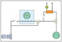
In a typical transcritical system, the hot gas leaves the compressor and enters the first three-way valve. Then, when the system is in heat reclaim mode, the gas will travel to the heat exchanger — most commonly a tube-in-tube or plate heat exchanger, where it is cooled down to as low a temperature as possible. From the heat exchanger, the now cold gas will travel through the second three-way valve. This valve directs the gas through either the air-cooled gas cooler, where the gas is further cooled before entering the high pressure expansion valve, or directly into the high pressure expansion valve.
High Pressure Safety & Load Control Strategy
It’s important that the system be designed to accommodate its higher operating pressures. There can be up to four levels of high pressure protection installed in the system: a safety valve, a pressure switch, an electronic soft pressure switch and a gas cooler operating at maximum working pressure with electronic settings. These items must be selected and set up in a way that they will not conflict with one another or affect normal system operation.Also critical is the development of a control strategy that can cope with the varying conditions experienced to meet the system’s heat reclaim objective. This can be addressed with the following methods: variable pump speed on the secondary side; variable fan speed on the gas cooler; high pressure; bypass of gas cooler. The following five steps provide a brief description of one possible method to address the need for control at varying loads. The complete process — from no reclaim to full reclaim — consists of four to five steps, and, ultimately, depends on system design. The base level is normal cooling with no heat reclaim.
IN STEP 1: the pump is turned on. There are different ways to control the pump speed, but, normally, speed is controlled to maintain a fixed temperature out of the heat exchanger. When the pump is at minimum speed and, in the water circuit, the flow switch is on and the temperature is below the high pressure limit, the three-way valve is turned. The pump speed is adjusted so the temperature set point is satisfied.
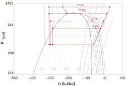
IN STEP 2: the pump is running according to the temperature set point, but the pressure is increased to make more heat available at the required temperature. This is done by increasing the set point in the high pressure controller and thereby closing the high pressure expansion valve. The higher pressure increases the compressor’s work, but also contributes a significant increase in the heating capacity. (See Figure 2.)
Heat rejection in the gas cooler remains a big part of the system’s total heat rejection. Since it is not possible or efficient to further increase the pressure, the heat rejection has to be limited to get more heating capacity out of the system.
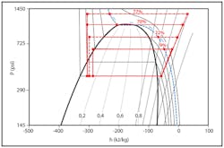
IN STEP 3: the set point for the fans is gradually increased until the fans have stopped. This decreases the heat rejection from the air-cooled gas cooler, which will result in a loss of cooling capacity, but the system will compensate by increasing compressor capacity. (See Figure 3.) Even when the fans are stopped, the natural convection of the gas cooler is enough to remove some capacity from the system.
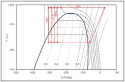
IN STEP 4: the gas cooler is bypassed to avoid natural convection and, thus, heat rejection from this part of the system. Similar to Step 3, this reduces the cooling capacity but the system compensates by increasing compressor capacity. At this point no heat is rejected to the ambient and the system will basically operate as a heat pump system.
IN STEP 5: all heat put into the system has been reclaimed. If the heating demand is still not satisfied, the load on the cold side of the system will need to be increased. This can be done by adding an extra evaporator that extracts heat from the ambient.
Design Challenges
Parallel to its benefits, heat reclaim also presents some significant design challenges for a transcritical system that differ from those uncovered during the design and installation of a conventional refrigeration system. As experience with heat reclaim evolves, however, new approaches are being found to common challenges.
Condensing in the Heat Reclaim Heat Exchanger
Since it’s possible to design a partial reclaim, the CO2 can be partially condensed in the heat reclaim heat exchanger. When the system uses more than one heat exchanger, the strategy becomes more complex. One potential problem is liquid build-up in part of the system. When this occurs, gas pressure eventually forces the refrigerant to ‘shoot’ into the system at high velocity, which can severely damage parts of the system. This problem can be resolved in several ways:
• The system can be forced into transcritical mode when there is a need for heat reclaim. This will reduce the efficiency of the system, but the operation is safe because there is only one phase.
• The inlet water temperature can be kept high enough (i.e. 86F) to ensure condensation is not possible. This will not force the system to run in transcritical mode, but will still reduce its efficiency. This control strategy can be made with a mixing loop on the water side.
• The pressure in the system can be controlled in a way that will keep the superheat out of the heat reclaim heat exchanger at a high enough temperature to ensure condensation is not taking place. This is a safe and most efficient way to control the process.
• Verify that the temperatures between heat exchangers are at an appropriate level.
Charge Variations
The average density of CO2 in the gas cooler varies by about a factor of two under different conditions. However, in a heat reclaim system, the removal of heat causes the density of the refrigeration gas to increase before it reaches the gas cooler, which results in a subsequent increase of mass in the gas cooler. Therefore, the internal volume of the gas cooler has to be reduced to a minimum without compromising the performance of the system. This can be done by choosing small diameter tubes for the gas cooler.
Conclusion
Designing heat reclaim functionality into a transcritical CO2 system is a viable and attractive alternative to heat reclaim in an HFC-based system due to the physical capabilities of CO2. Both the efficiency and temperatures that can be obtained are higher compared to HFC heat reclaim technology, which significantly benefits the application and its objectives.
When utilized properly, the transcritical system with heat reclaim could, in some designs, eliminate the need for an HVAC system altogether, significantly reducing design costs for the facility. In most cases, however, the reclaimed heat will be used as a complementary asset to standard building comfort control, thus reducing energy costs of the HVAC system by taking advantage of the heat available in the refrigeration system.
Chris Brown is applications engineer and Jae Kyun Chon is OEM key account manager for Danfoss.


