Vaneaxial Fan Reduces Installation and Energy Costs for Chicago Firm
Choosing the Right Fan in the Air Handling Unit for Renovated High Tech Headquarters
A major national high tech firm moved its Chicago headquarters to the Fulton Street area as part of a neighborhood revitalization effort. The building, which was formerly a meat freezer locker, was gutted and completely renovated. When selecting the rooftop air handling unit, engineers were looking for a design that minimized noise, because the rooftop area contains an outside garden and employee snack bar.
The original design for the air handling unit included a fan wall for both supply and return. For the past 10-15 years, the fan wall concept has been the favored approach for high rise building ventilation. The idea is that the ventilation unit can still operate if one fan happens to go down. Also, the fan unit length is shorter, reducing the overall length of the air handling unit. The smaller footprint can save on the total air handling unit cost.
BTU Company, Inc, a professional manufacturer’s representative firm in the HVAC and refrigeration industries, and BBM Engineering, worked with the project engineering design firm WMA Consulting Engineers, Ltd. to instead consider the use of JM Evase Vaneaxial fans by Howden American Fan Company.
The sales rep explained that vaneaxial fans perform better and can save on energy costs. He performed a calculation showing that the static pressure on the fan wall is higher than a vaneaxial fan, due to losses on the outlet of the fan. This increased the overall total motor horsepower of the fan wall compared to the vaneaxial fans.
Table 1 shows the comparison between the vaneaxial design and the original fan wall design. The vaneaxial design resulted in 371.91 horsepower in operating load savings.
|
Table 1 – Comparison of Fan wall vs Vaneaxial 150,000 cubic feet per minute (CFM) total |
||||||
|
|
Number |
Array |
Each fan performance |
Total building load for 3 AH units |
BHP Saving (operating load) |
|
|
Fan wall – 305.97 operating HP load |
21 |
3 (fans) high x 7 (fans) wide |
7,143 CFM @ 6.718” external static pressure (ESP)* (*extra static plenum loss) 14.57 BHP/fan - 15 HP motors |
945 HP |
--- |
|
|
Vaneaxial fans – 182 BHP operating HP load |
2 |
2 fans (50” ID) |
75,000 CFM @ 6.0” total pressure |
91.00 BHP/fan 100HP motors |
600 HP |
371.91 HP |
Unique Evase Design Reduces Turbulence and Noise
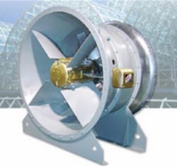
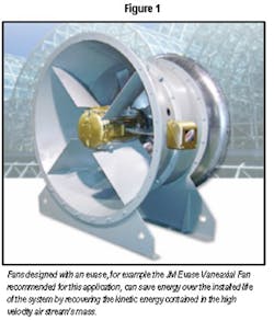
The team also designed the inlet and outlet of the vaneaxial fan in the air handling unit to be more efficient and quieter using an evase casing, a piece of the fan casing that increases in size as the air moves through the fan. This option makes the fan more compact. The design, shown in Figure 1, provides a static regain and reduces the overall brake horsepower (BHP). It reduces turbulence through the fan on the downstream and lowers noise.
Since you don’t have to specify a discharge cone for the system, the fan’s overall footprint is reduced. Air velocity is low enough for outlet damper and shutters to operate without fear that these relatively sensitive components will be destroyed by high velocity flutter.
The evase fan design incorporated integral stationary anti-rotation guide vanes to enhance the regain effect by slowing the rotation imparted to the airstream by the fan impeller and recovering rotational energy losses, while reducing fan noise generation. A separately formed impeller casing was used to ensure uniform minimal tip clearance for full pressure development.
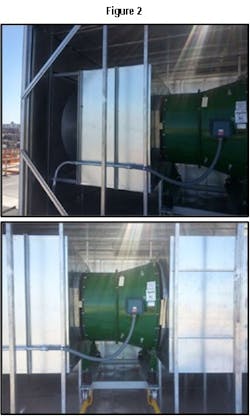
The design for this custom air handling unit also includes an inlet trap with a special bullet (pod) inside to direct the air. With vaneaxial fans there is a hub and blades are attached to the hub, the bullet is designed to be the same size as the hub, so there are no concerns about vortices around the hub. A specially made sound trap with turning vanes designed by BBM Engineering helps reduce the sound as it goes down into the rest of the building.
Figure 2 shows the custom air handling unit designed for the Chicago project. The top


