12 'Must-Dos' on a Furnace Clean and Tune

Cleaning and tuning a furnace today is a much more involved task than it was in the past. "Old school" clean and tunes may have involved taking out the pilot burner and cleaning the orifice, and removing rust from the main burners with a wire brush. The thermocouple may have been cleaned with steel wool. Those procedures were relevant and effective in their day, but today's advanced technology and high-efficiency furnaces require more precise procedures to ensure optimum performance and a trouble-free life.
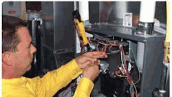
Here are 12 things you must do to properly clean and tune newer LP or natural gas furnaces.
1. Check the igniter by using an ohmmeter. Measure the resistance through the igniter. If the furnace has a silicon nitride igniter, you should see 11 to 17 ohms. If the furnace has a carbide igniter, you should see 50 to 100 ohms. If the reading is outside these parameters, the igniter should be replaced. Remember that you need to test the igniter when the igniter is cold and furnace is not firing.
2. Check the flame sensor (if present). Hook up your multimeter in series with the flame sensor and the sensor wire, and fire the furnace in a heat cycle. Your readings should be 1.5 to 4 uA (some manufacturer’s control systems only need 0.5 uA, so check the manual for the system you’re testing). When sensor tests at less than 1 uA (or less than 0.5 uA on some systems) you’ll see nuisance problems, and soon it will stop sensing completely.
A stiff-bristled brush can be used to clean superficial rust or soot from the burner face. Use air pressure or dry nitrogen to blow out the burners and burner vestibule area. A dirty crossover can cause delayed ignition, which in turn can cause high carbon monoxide (CO) on start-up and during the first 60 seconds of run. Replace severely rusted burners.
4. Inspect the heat exchanger for excessive rust, cracks, or holes. Visual inspection is always the best, but requires training and practice. There are tools available to assist, such as inspection cameras and dye penetration inspection systems. Inspect the metal flue for rust or holes, and make sure it’s supported properly.
5. On condensing 90%+ furnaces, blow out the condensate line. Remove or blow out the P-trap and pressure tubes to remove debris. Condensate lines have become the source of a common issue for 90%+ furnaces: long run times in very cold weather can cause the pressure switch to lock out. Then, by the time the service technician gets to the house, the water has drained out and everything is working again. This is one of the little items that can cause homeowners to become frustrated when they pay for a cleaning and problems like this occur.
6. Check the system static pressure. Determine if you're working on a system with a non-variable-speed motor or a variable-speed motor. A system with a non-variable-speed motor will have maximum design total external static pressure (ESP) of 0.50-in. wc. A system with a variable-speed motor will have a maximum design ESP of 0.80-in wc. On an 80% induced-draft furnace you need 130 cfm of supply air per 10,000 Btu. On a 90% furnace you need 150 cfm of supply air per 10,000 Btu. Refer to a fan chart to set the correct cfm for the furnace so you can complete setting gas pressure and proper heat exchanger temperature rise (if the system has a bypass humidifier, make sure you close the damper during this process).
7. Perform a combustion analysis. Start your combustion analyzer while outside the home for proper calibration. When starting the furnace, measure and record the highest CO level during the first 60 seconds of operation. The CO level will range from 100 to 400 ppm on natural-draft furnace, and 100 to 1,000 ppm on a 90% condensing furnace. Each manufacturer will be a little different, and experience will help you understand if there’s an issue with a particular unit. The CO level should then fall below 100 ppm within three minutes after starting the furnace. Operating CO levels should be between 0 and 99 ppm and remain stable. If your CO starts to slowly climb during run cycles, this is a sign of a safety issue and requires further testing.
Oxygen (O2) levels should be between 6% and 9% and should remain stable. You will commonly see furnaces that are set at factory levels higher than this, and in order to get maximum efficiency you’ll need to adjust to the 6% to 9% O2 level.
Immediately after shut-down of the furnace you should see the CO levels drop. If you see them increase for a short period, the furnace's gas valve may not be closing fast enough. After you've completed step #9 below, you will come back to verify all these measurements again.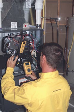
9. Check and adjust the gas pressure. Gas heat content is lower than typical design. Manufacturer’s installation manuals for natural gas furnaces list the maximum Btuh input, which assumes a certain heat content in the gas at 3.5-in. wc manifold pressure. The best way to measure the gas pressure is to clock the meter to verify that the orifice is the proper size and you can set the correct gas pressure (note that it isn't possible to clock a meter with an LP furnace). Furnace manufacturers typically list in their installation manual for natural gas that a range of 3.2 to 3.8-in. wc is needed for proper combustion because of the variation of gas Btu content. As it usually isn't very easy to have the proper assortment of burner orifices, you can typically achieve proper combustion for maximum safety and efficiency by adjusting the gas pressure.
10. Check for gas leaks. You can use either soap bubbles or an electronic leak detector, but keep in mind that some electronic leak detectors will produce a false-positive from certain brands of pipe dope and soap bubbles.
11. Look for proper support of the vent pipe. On condensing furnace installations, low spots will accumulate water and retard venting, possibly resulting in trips of the pressure switch. Pipe-support hangers should be placed every 3 ft. on PVC. Also inspect for leaking or loose fittings. If the PVC exits the side of furnace and has a rubber boot attaching the PVC to the inducer, be aware that boot isn't designed to support the pipe and should have a support strap directly outside the furnace.
12. Set the heat-off delay. For best reliability and maximum efficiency, set the heat-off delay to the longest time available (typically 180 seconds). Carefully following these 12 steps will help you perform a superior furnace tune-up that will help ensure that your customers stay safe and warm all winter — even in Minnesota.
Corey Hickmann is president and Jason Gillem is a service technician at Comfort Matters Heating & Cooling, Inc., Hanover, MN. Hickmann can be reached at 763/493-2665 ext. 223, or by e-mail at [email protected]. Comfort Matters was a winner in the 2011 Contracting Business Quality Home Comfort Awards. See their winning project at http://bit.ly/comfortmattersqhca