Service Clinic: How to Measure Flow Through a Water Balancing Valve
Airflow from a supply register is easy to measure. Cover the grille with a balancing hood, and the airflow measurement appears on the screen. Measuring water flow isn’t as easy. Since a water system is closed, balancing valves must be installed into the piping before you can you measure and adjust system water flow.
Let’s take a look at how to measure flow through a water balancing valve.
Most technicians are stronger on measuring airflow than waterflow. This short article is intended to introduce the basic principles of balancing valve waterflow measurement.
How the Test Works
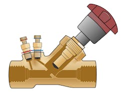
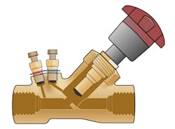
A balancing valve is a fitting installed in a hydronic system. It has two test ports that allow you to insert test probes into the system water stream. These probes are attached to a water manometer that reads the water pressure before and after the balancing valve.
The manometer displays the pressure drop across the valve. Using valve manufacturer information, you convert the pressure drop across the valve to the flow gallons per minute (gpm).
Testing Accessories
As with most mechanical tests, there are a few accessories you’ll need before you can successfully measure flow through a balancing valve.
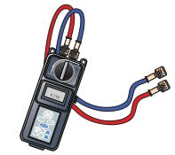
The test instrument you need is a hydro-manometer. It operates like an airside manometer by measuring pressure. A hydro-manometer measures water pressure throughout the system.
Required accessories for the manometer include:
- Two hoses that connect the manometer to the balancing valve
- Needle-like test probes installed onto the hoses to pierce the semi-sealed test ports contained in the balancing valve. Tiny holes in the probe tips allow pressures in the valve to transfer into the manometer where pressure is displayed
- An assortment of fittings is needed to connect the probes to the valve.
- You will also need the manufacturer’s flow calculator that matches the valve being tested. There are other methods to interpret the pressure reading, but we won’t discuss those in this article.
Test Conditions
A few conditions need to be right for the test to be effective:
- The system pump must be functioning during the test
- The system controls must be set to call for full heating or cooling, assuring full flow
- The water or fluid in the system, and the strainer (water filter) should be clean.
- The system must be purged of any air in the water.
- The manometer hoses must be filled with the system fluid before the test is taken.
- Assure the water balance valve is properly installed so you have access to attach the hoses to the balancing valve.
- The manometer must be calibrated annually, then zeroed before connecting to the valve.
- Ideally, the balancing valve is properly installed with a minimum of 10 or more diameters of straight pipe before the valve and two or more diameters of straight pipe after the valve, or as the valve manufacturer directs.
Test Procedure
Depending on the hydro manometer used, adjust the manifold valves on according to manufacturer’s instructions. Set the meter or the manifold to read flow through a balancing valve.
The essence of this test is to read the water pressure before and after it passes through the valve. Each valve has a fixed orifice that creates a certain pressure drop as water passes through it. The measured pressure drop over the valve is compared to data published for the valve that interprets flow (gpm) through the valve.
Here are the steps to complete the test:
1. Attach the positive pressure hose from the manometer to the ½-in. tap in the flange upstream of the balancing valve. Insert the probe onto the hose end. Then insert the probe into this test port. Hand tighten the brass fitting to the valve test port.
2. Next, fasten the negative pressure hose from the manometer by inserting the probe into the downstream ½-in. flange on the balancing valve.
3. Take the pressure reading by pressing the test button on the manometer. The instrument displays the pressure drop across the balancing valve.
4. Then read the degree setting on the balancing valve handle.
5. Plot the pressure drop with the corresponding degree setting of the balancing valve on the manufacturer’s flow calculator to interpret gpm.
6. Compare the measured gpm to required system gpm.
7. If needed, adjust the valve setting to increase or decrease flow.
8. Once the design water flow is achieved, lock-down the valve by removing the cap on top of the handle and closing the screw until tight. Snap the cap back onto the valve handle.
When you assume the volume of water flow through a system it can create many problems when troubleshooting and diagnosing HVAC system performance. According to many HVAC company service managers, up to 70% of unresolved service issues can be quickly solved once the flow value through the system is known.
Temperature rise calculations used to verify acceptable system performance often fail because of water flow assumptions. Water system diagnostics are often incorrect or misleading based on this assumption.
Many smaller hydronic systems are built without balancing valves. This cost cutting decision leaves the system frequently operating well below the intended results. Equipment installed in these systems are forced to operate outside of manufacturer published specifications. This means they regularly perform at half their laboratory-rated capacity and efficiencies under these conditions.
Knowing the water flow through a hydronic system is a real game changer. Perhaps this information will arouse your curiosity and move you to plug the leak in your quest to better diagnose the water side of HVAC systems.
Rob “Doc” Falke serves the industry aspresident of National Comfort Institute, Inc., an HVAC-based training company and membership organization. If you're an HVAC contractor or technician interested in a free test procedure to measure and plot pump flow,contact Doc [email protected] call him at 800-633-7058. Go to NCI’s website at nationalcomfortinstitute.com for free information, articles, and downloads.
About the Author
Rob 'Doc' Falke
President
Rob “Doc” Falke serves the industry as president of National Comfort Institute an HVAC-based training company and membership organization. If you're an HVAC contractor or technician interested in a building pressure measurement procedure, contact Doc at [email protected] or call him at 800-633-7058. Go to NCI’s website at NationalComfortInstitute.com for free information, articles and downloads.


