Thank you for your responses to my duct sizing article from the last Hotmail newsletter. I have seen firsthand the desire many of you have to improve your duct systems, and I am eager to provide more information in this follow-up article. Let's take a closer look at duct sizing in the field.
A duct system has one simple mission; direct all the air from the equipment into each room and then back to the equipment.
The Great Air Loop
A fan rotates and creates a suction and a discharge pressure. The discharge pressure pushes air through the duct system into the home. Then the suction pressure pulls the air into the return duct and back to the fan. The great air loop fills and empties the air in the house about once every 10 to 15 minutes.
Most of the air's journey through this air loop is through the duct system. Success depends on duct size, installation, and how much they resisted airflow.
Consider Fan Limitations
Each fan is sized to deliver airflow matching the system's heating or cooling capacity at a specified maximum rated pressure. If the resistance to airflow through the ducts, filter, and coil is too high, the fan can't move the required airflow, and the system's heating and cooling capacity decrease.
You can find the fan maximum pressure capacity listed on the air moving equipment nameplate. In residential systems, the most common is .50 inches of water column (in. w.c.). That isn't much pressure to work with.
A study of well-operating residential systems shows the filter and coil consume about 60% of the fan capacity. This leaves only about 40% of that capacity to move air through the ducts. With a .50-in. w.c. rated fan, only .20-in. w.c. of pressure remains to push and pull air through the ducts.
To help customers better understand duct design pressures, consider using the weight of a jellybean. When you design a residential duct system, you can ply work with pressure equal to four jellybeans in the palm of your hand. Two jellybeans of pressure push air through the supply duct, and two jellybeans of pressure pull air through the return duct.
If duct pressure is too high, airflow decreases and forces the system to operate outside its specifications. The system won't work nearly as well as it should. When heating and cooling capacity plummet, utility bills skyrocket, and comfort cannot be achieved.
First, How Much Air?
Before you can begin to size a duct, you'll need to know the required airflow that duct must move. So, when sizing ducts entering or exiting the equipment, size them to move the total amount needed of fan airflow.
If a supply trunk duct serves three-branch ducts, add together the airflow needed for each branch duct. Size the trunk duct to carry that total volume of air.
The other end of the duct system distributes air into or out of each room. Before sizing end-run ducts, you'll need to know the required room airflow. Traditional load calculation software is available. Refer to this article, ncilink.com/ReqAirflow, for more information.
Friction Loss and Ductulators
Duct sizing calculators, or ductulators, are the most common tool used to design ducts. The challenge with ductulators is which friction rate to use. Interestingly, most ductulators have a big black mark over the .1-in. friction rate scale.
Unfortunately, field airflow test data shows that using a friction rate of .1-in. produces duct systems that are far too restrictive. This typical duct design factor, coupled with poor installation practices, often produces duct systems delivering dangerously close to only half the required airflow.
My personal experience in duct sizing brought me face-to-face with this reality many decades ago. Our family company was more than 40 years old at the time. We believed our primary strength was great duct systems. Then the day came where my first balancing hood arrived. Imagine how I felt when the system I had just designed and installed only delivered 58% of design airflow!
We removed the new duct and replaced it with larger duct. I balanced my first system, walked away filled with questions, and faced a challenging year ahead seeking answers.
That day, I learned .1-in. friction rate on a ductulator did not deliver the airflow we believed it should. Immediately, our duct design methods got overhauled. Over the years, when we used the ductulator on residential jobs, we typically chose a .05-in. friction rate for flex duct, .06 for metal pipe, and .07 for rectangular duct.
If you use software to design your ducts, stop smirking -- the same principle applies to all design. Unless you measure installed system airflow and static pressures, you have no evidence your design performs in the field. Measurement is the only verification that an installed duct system delivers designed airflow.
Bigger Ducts?
FACT: The average residential duct system is too small. Once again, field testing shows typical static pressures exceed 150% of maximum rated fan capacity. Plus, delivered airflow at the grilles hovers at or below 300 cfm per ton.
Bigger ducts are better because they deliver more comfort and efficiency. Stop worrying about maintaining high air velocity -- that's a left-over idea from the 1950s that should have been buried in the 70s.
So, what duct design method should you use? Surprisingly, most duct design methods and software can produce well-operating duct systems. The number one mistake that ruins most duct designs is underestimating the friction rate. Always adjust friction rate calculations upwards until installed system measurements consistently agree with design airflow values.
Simple In-Field Duct Sizing
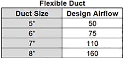
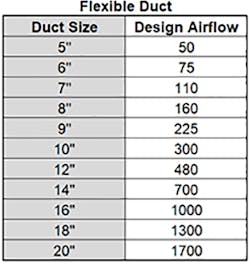
One in-field duct sizing method proven effective is a National Comfort Institute (NCI) table created in 2005. It was created by gathering and averaging thousands of airflow measurements from operating, balanced HVAC systems in the field. It includes rectangular and round sheet metal and flexible duct sizing recommendations. You can receive a copy of this table. The offer is at the end of this article,
The design airflow in this table may be less than your current design method suggests. In that case, if you choose to use this table, you will find a substantial increase in system airflow and reduced static pressures in your new systems.
Here are a few steps to follow if you choose to use this duct design method:
1. In the field, sketch out a rough duct schematic of the system using your preferred type of duct system. Show the equipment and each supply and return duct and grille. Indicate the room name and the required airflow. List the equipment size and required airflow.
2. Assure the installation follows best practices; reasonable duct lengths and fittings, adequate duct access.
3. Size the last duct in each run connected to a register or grille first; select the duct size to deliver the required CFM to each grille, according to the duct material used. The airflow shown on the chart is the maximum CFM expected when selecting that duct size.
4. If a duct run is more than 30 feet from the equipment, increase the duct to the next larger size.
5. Continue to work back towards the fan. When two ducts join together and connect to a larger duct, add the airflow from both ducts, and size the trunk duct for that amount of total airflow.
6. Continue to size each duct accordingly throughout the remainder of the system, working back to the fan.
Once you finish the installation, measure system airflows, and pressures, then compare delivered airflow to your design. Design and installation are incomplete without field-measured verification.
Rob "Doc" Falke serves the industry as president of National Comfort Institute, Inc., an HVAC-based training company and membership organization. If you're an HVAC professional interested in a free duct sizing table, contact Doc at ncilink.com/ContactMe or call him at 800-633-7058. Go to NCI's website at nationalcomfortinstitute.com for free information, articles, downloads, and current training opportunities
About the Author
Rob 'Doc' Falke
President
Rob “Doc” Falke serves the industry as president of National Comfort Institute an HVAC-based training company and membership organization. If you're an HVAC contractor or technician interested in a building pressure measurement procedure, contact Doc at [email protected] or call him at 800-633-7058. Go to NCI’s website at NationalComfortInstitute.com for free information, articles and downloads.

