Our tech support team has received calls about air filter pressure drops that are off the chart -- often more than double the filter's rated pressure drop. This situation increases resistance to airflow. Today, we found a cause of the problem. Let's take a look at this recurring air filter problem and how you can solve it.
The Issue
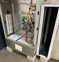
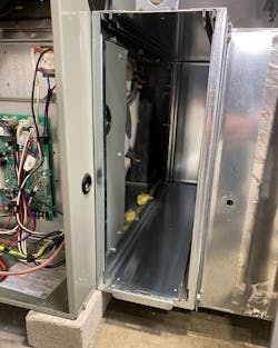
We found this specific problem in residential furnaces with shallow blower compartments. One recent manufacturing trend cuts off more than six inches from the front of the blower compartment. When a return drop taps into the side of the blower compartment, there is less available area for airflow to enter. The result is increased resistance to airflow and reduced system heating and cooling capacity.
For example, we inspected and tested two upflow 80,000 Btuh furnaces requiring 1200 cfm, with a maximum rated total external static pressure of .50 in. w.c. (inches water column.) Each furnace had a return drop tapped into the side of the blower compartment.
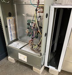
In the image to the right, notice the wall in front of the blower compartment was built back from the front of theUsually, 80,000 Btuh furnaces provide space to install a 16-in. x 26-in. filter or housing in this application. In this furnace, the largest opening that can be cut into the side of the blower compartment is 14 1/2 in. x 18 in.
This design flaw reduces the inlet size into the blower compartment from 416 sq. in. to 261 sq. in. This reduction causes a 38% decrease in the available area to move airflow into the furnace.
Static Pressure Testing
One of these typical furnace installations had a measured static pressure drop of .52-in. w.c. over the air filter and filter rack. This drop is more pressure than the fan can handle. The installed air filter had a rated pressure drop of only .16 in. at 1200 cfm. This means the system suffered from an excessive pressure drop of .37 in. This indicates an added restriction in the system.
The reduced size of the inlet into the blower compartment caused the additional .37-in. pressure drop. The entire volume of system airflow was forced to pass through a reduced portion of the filter.
The excess system pressure caused by this defect consumed all the fan's available total external static pressure of .50 in. There was no fan pressure left to move air through the cooling coil and duct system.
Fan Watt Draw Reduces Installed System Efficiency
Fortunately, most of the systems tested had equipment that included high-quality ECM (Electronically Commutated Motor) blowersUnfortunately, the blower ramped up to maintain the required airflow, and the motor Watt draw skyrocketed. This increase in watt consumption will seriously reduce installed system efficiency.
When the furnace efficiency was tested in the lab, the fan motor watts were less than 180 Watts.
However, we found the measured blower motor watts quadrupled to more than 700 Watts under field conditions! In this scenario, the excessive blower motor watt consumption, added motor heat, and reduced system Btu delivery. This defect reduced the installed system EER from 13 to below 9.
Most service companies will not detect this unseen efficiency. The penalty: homeowners pay added utility costs over the system's life, receive poor air filtration, and usually suffer discomfort in their homes.
Field Solutions to Short Blower Compartments
Every problem that deteriorates the performance and efficiency of an HVAC system has a solution. The trick is to discover the problem and other defects. This skill set takes testing and diagnostics beyond the average technician's knowledge and ability. Here are several options that will resolve the short blower compartment issue:
Measure system air pressures – Before you begin to make changes in your installation, measure the static pressure drop across the filters in the systems you install with short blower compartments. Perhaps you perceived this potential problem ahead of time and modified your installation practices to avoid high pressure and low airflow.
Select furnaces with a deeper blower compartment – Avoid the problem altogether. Most residential furnaces are built to accept the full depth of a filter that can operate correctly.
Install a return plenum below an up-flow furnace to provide adequate space for filter surface area necessary when using a return drop installation.
Design and build return drops with a filter housing upstream from the furnace with room to install a filter, so airflow is not restricted. This allows you to install a right-sized filter.
Install multiple return air filter grilles. Doing this allows you to increase filter surface area, use a more efficient air filter, and maintain the needed low resistance to airflow. If you decide to use this repair, ensure the return ducts are sealed, so air doesn't bypass the filter.
Perhaps in your experience, residential furnace installations include return duct drops tapped into the side of the furnaces. If so, when you purchase furnaces with short blower compartments, use one of the solutions described in this article to be sure you serve your customers well.
Rob "Doc" Falke serves the industry as president of National Comfort Institute, Inc., an HVAC-based training company and membership organization. If you're an HVAC professional interested in a free procedure to measure filter pressure drop, contact Doc at ncilink.com/ContactMe or call him at 800-633-7058. Go to NCI's website at nationalcomfortinstitute.com for free information, articles, downloads, and current training opportunities.
About the Author
Rob 'Doc' Falke
President
Rob “Doc” Falke serves the industry as president of National Comfort Institute an HVAC-based training company and membership organization. If you're an HVAC contractor or technician interested in a building pressure measurement procedure, contact Doc at [email protected] or call him at 800-633-7058. Go to NCI’s website at NationalComfortInstitute.com for free information, articles and downloads.


