How to Balance an HVAC System with Low Airflow
The basic definition of a properly air-balanced system is when all airflow is adjusted to within ±10% of design. Let's take a look at a few simple calculations and adjustments you can make when fan airflow is low and conditions are less than perfect. Be assured you can still deliver the best-balanced system possible.
Set Fan Airflow
The fan is the air factory for the system. Airflow into and out of the fan sets the maximum amount of air with which you must work. Unfortunately, when you arrive on the job as the balancer, the installation is done, and a wide variety of obstacles may prevent the fan's ability to move needed airflow.
The fan is the air factory for the system. Airflow into and out of the fan sets the maximum amount of air with which you must work.
Common difficulties include poor design and installation practices, undersized ducting, restrictive fittings, tight installation conditions, and overly restrictive filters. While each of these problems can be surgically repaired, fixing each defect is not the balancer's job; it's the installer's responsibility.
Measure the total volume of air the fan moves by traversing airflow into or out of the fan. You can also plot airflow on the manufacturer's fan table using measured fan rpm and total external static pressure.
Ideally, you can maximize fan airflow by increasing the fan rpm. Do this by setting dip switches, swapping fan wiring ports, adjusting variable frequency drives, or adjusting pulleys.
Reality will teach you that even with your best effort, there are days when the most total-airflow you can get from the fan may only be 80% of required airflow.
Reality will teach you that even with your best effort, there are days when the most total-airflow you can get from the fan may only be 80% of required airflow. Say you're balancing a 3-ton system. Required airflow is 1200 cfm, and all you can squeeze out of the fan is 960 cfm or 80% (1200 cfm/960 cfm = 80%).
Fear not, a successful balancing job is still possible, and you're the one to make it happen.
Inspect the System
With fan airflow set to its maximum available capacity, take a few minutes, and inspect the ducts. None of those should be disconnected, smashed, or pinched. Also, be sure ducts are well suspended and straight.
Verify balancing dampers are installed and open, and air flows freely through the ducts. Make minor adjustments within your scope of work as the air balancer.
Prepare the Balancing Report
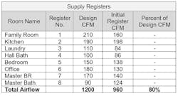
A good basic air balance report organizes airflow design information to help you analyze test data as you collect it. In other words, as you measure and record field information, it fits together and tells its own story, guiding you toward what to do next.
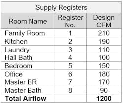
Record each room name, number the registers in the order you plan to test them, and list each register's design or required airflow at total design cfm.
Measure the Supply Register Airflows
Next, measure and record airflow from each supply register. Add together the register airflows and compare them to design CFM. Evaluate each register's airflow. Is airflow lower or higher than it should be?
Notice in the balancing report below the total supply register design cfm is 1200, but the actual airflow being delivered through the supply registers is only 960 cfm.
Divide 960 cfm into 1200 cfm to calculate only 80% of the design cfm is being delivered through the supply registers. That's all you have.
Since the total supply register airflow available into this home is only 960 cfm, your job is to balance the system to give each room its fair share (80%) of available airflow.
Calculate Each Room's Share of Available Airflow
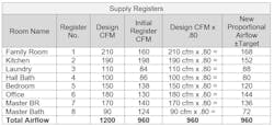
To find each room's share of available airflow, multiply the room's design cfm by 80%. This will ensure that each supply register will deliver even temperatures into each room and an equal percent of required ventilation after balancing.
For example, the kitchen design cfm is 190 cfm. Multiply 190 cfm by 80% (.80) to discover the kitchen's share of available supply register airflow is 152 cfm.
Continue to calculate each room's share for supply register airflow by multiplying its design airflow by 80% (.80).
Balance Each Supply Register to New Proportional Airflow Target
With a new proportional airflow target for each supply register calculated, it's time to make final balancing damper adjustments. Remember, the fan is producing all it can, so your goal is to close down dampers to direct the needed airflow to each supply register.
Begin with registers having the highest airflow percentage. Close the balancing damper to the kitchen and reduce airflow from 198 cfm to 152 cfm. This will force additional airflow into supply registers needing more airflow.
Usually, one or two passes through the system will be enough to adjust each supply register within ±10% of the new airflow target.
Make Final Calculations and Mark Balancing Dampers
Review the completed balancing report and verify your math. A final check requires you to calculate the percent of proportional airflow target. Divide the final register cfm by the new proportional airflow target. This will assure each supply register airflow is within ±10%.
With each supply register adjusted, go ahead and mark the location of each damper setting. This may sound premature, but it confirms the principle that even though total airflow through the fan is only 80% of design, the pressures and proportional airflows will continue to deliver its prescribed percent of airflow, even when airflow may be increased in the future as installers make system repairs.
Notice in the far-right column each supply register is balanced within ±10%. Equal temperatures and proportional ventilation have been maximized under the current conditions of the system.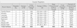
The principle of proportional system balancing with low airflow has many applications that apply to daily balancing and airflow troubleshooting. Sure, the test procedures and math are challenging the first few times you try it. But building experience and skills are essential to becoming a balancing professional.
Rob "Doc" Falkeserves the industry as president of National Comfort Institute, Inc., an HVAC-based training company and membership organization. If you're an
About the Author
Rob 'Doc' Falke
President
Rob “Doc” Falke serves the industry as president of National Comfort Institute an HVAC-based training company and membership organization. If you're an HVAC contractor or technician interested in a building pressure measurement procedure, contact Doc at [email protected] or call him at 800-633-7058. Go to NCI’s website at NationalComfortInstitute.com for free information, articles and downloads.