Thank you for your responses to my last CB HotMail article “Prescription for Service Manager Stress Relief.” I received many comments about how airside testing and diagnostics have been the answer to many unseen customer complaints across the country. Per your requests, we’ll take a deeper look into airside diagnostic solutions you can benefit from.
Refrigerant Charge and Temperature Diagnostics
The previous article reported service managers who add airflow diagnostics to their services, could solve 50%-70% of their service tech’s long-standing problems. We only considered the effects airflow diagnostics had on refrigerant and temperature diagnostics. Let’s investigate further.
Static Pressure
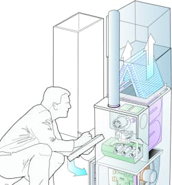
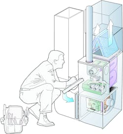
Static pressure testing is quick and the test instruments are relatively inexpensive. This testing offers direct diagnostics to pinpoint hidden airflow problems that otherwise go undetected. Another huge benefit of measuring static pressure: Your diagnostic abilities constantly increase.
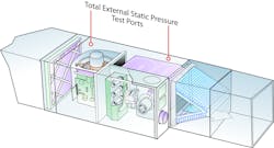
Total External Static Pressure (TESP) – This test takes a few minutes to conduct. TESP can be compared to human blood pressure and is the foundation for all airside diagnostics. It provides a number that allows you to assess the overall airside performance of the system.
TESP is determined by adding together pressures in the airstream where air enters and exits the air-moving equipment. This pressure reading can also be used with fan speed or RPM to plot fan airflow.
Filter Pressure Drop – As filter efficiency increases, the filters themselves often become more restrictive than many fans are designed for. Filter pressure drop is found by measuring the pressure in the airstream just before and after the air filter. Subtract these two pressures to find the filter’s resistance to airflow. Filter pressure drop normally should not exceed 20% of fan rated pressure.
Duct System Pressures – This test offers a quick assessment of the duct system’s resistance to airflow.
To find return duct pressure, install a 3/8-in. test port before air enters the filter and measure — that’s it. This single pressure also should not exceed 20% of fan rated pressure in most cases. If it does, the duct may be damaged, undersized, or poorly installed.
On a gas furnace system, supply duct pressure is measured after air exits the external cooling coil. The same rule applies: this pressure should typically not exceed 20% of fan rated pressure. If it does, the restriction of the supply duct is excessive, and repairs may be needed to increase airflow.
Static pressure is the initial “go-to” test to help you diagnose the overall airside system performance. Once you begin to add pressure testing to your diagnostics, the unseen defects you’ve been overlooking for years will clearly come into view.
Room Airflow Testing
Once the equipment airflow meets manufacturer specifications, the next set of air-side diagnostics addresses room airflow issues.
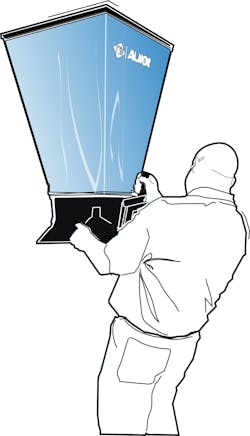
When customers complain about individual rooms, start is measuring room airflow with a balancing hood. Then compare measured room airflow to required room airflow. Normally, uncomfortable rooms only receive 30% to 40% of their design airflow.
Your customers easily understand this problem and will want you to complete duct renovations that correct the issue.
In the previous article, we discussed how temperature diagnostics are completely dependent on the amount of air through the system. In the same manner, airflow diagnostics are not complete without temperature diagnostics.
You will find some systems suffer from significant duct temperature losses. If the balancing hood test confirms the right amount of air entering a room, add temperature to your diagnostics.
Measure air temperature leaving the equipment, then measure the air temperature leaving the supply register in the room. In cooling mode, if this is more than a 2ᵒF temperature difference, the loss is directly affecting room cooling. In heating mode, a loss of more than 5ᵒF may have the same effect on a room’s temperature.
Always combine airflow diagnostics and temperature diagnostics to increase your accuracy.
Deeper into the Refrigerant Side
Several of your inquiries from the previous article wanted more information about air and refrigerant diagnostics.
Good refrigerant diagnostics are incomplete until you have good information about the three fluid flows affecting a cooling system. These include:
1. The volume of airflow through the indoor coil.
2. The volume of airflow through the condensing unit
3. And lastly, the volume of refrigerant through the compressor.
Each of these system properties are inseparably connected. Attempting to diagnose the refrigerant circuit without considering the airside before tapping into the refrigerant circuit, seriously reduces your chance of an effective diagnosis and solution.
The volume of airflow through the indoor coil — You obtain this information obtained by traversing the airstream into or out of the air moving equipment. You can also plot Airflow using the equipment’s fan performance tables or chart. If it differs from design, adjust system airflow and then continue with diagnostics.
The volume of airflow through the condensing unit – You can use several methods to verify the airflow volume. First, inspect coil cleanliness. If the coil is dirty, airflow will decrease. That has an immediate impact on the system temperatures. This must be corrected before refrigerant diagnostics can be completed correctly.
If either of the two system airflows decrease, an immediate impact will show up in refrigerant pressures and temperature. In other words, assuming airflow can kill your refrigerant diagnostics (and compressors, as well).
Enthalpy Change through the equipment — Before pulling out the refrigeration gauges, there is one more step to good refrigerant diagnostics. Measure the enthalpy change through the equipment.
We’re all used to measuring temperature change through a heating system. You simply measure air temperature entering and exiting the equipment and subtract to find the difference.
In cooling mode, dry bulb temperature measurement is not enough. You have to compensate for moisture in the air too. A unit of measurement called enthalpy replaces dry bulb temperature measurement. An instrument called a hygrometer is used to measure the enthalpy change through the equipment.
If the airflows are verified, the enthalpy change over the system is the key to refrigeration.
The hard truth is you don’t need to pull out refrigeration gauges until the airflow is known and the enthalpy change through the equipment is measured. With airflow ± 10% of design, an enthalpy change of 6.0 to 6.6 across the coil verifies good performance of the refrigerant side. All this while leaving your gauges in the truck.
Rob “Doc” Falke serves the industry as president of National Comfort Institute, Inc., an HVAC-based training company and membership organization. If you're an HVAC contractor or technician interested in a free test procedure describing how to measure and interpret enthalpy change, contact Doc at [email protected] or call him at 800-633-7058. Go to NCI’s website at nationalcomfortinstitute.com for free information, articles, and downloads.
About the Author
Rob 'Doc' Falke
President
Rob “Doc” Falke serves the industry as president of National Comfort Institute an HVAC-based training company and membership organization. If you're an HVAC contractor or technician interested in a building pressure measurement procedure, contact Doc at [email protected] or call him at 800-633-7058. Go to NCI’s website at NationalComfortInstitute.com for free information, articles and downloads.


