
The most important diagnostic truth about a system is that you can determine the amount of air the system fan is moving. Let’s take a look at how fan airflow can be plotted in less than five minutes to open the door to a new level of diagnostics and troubleshooting.
Gather Fan Performance Data
All equipment manufacturers provide fan performance data with each piece of equipment. Having this data at your fingertips is the key to quickly determining fan airflow.
To be well prepared for this new level of diagnostics, begin collecting copies of the fan data found in most installation instructions for the equipment your company installs and services.
You can take a picture of these documents and place them in a folder on your phone -- or gather these charts in a paper folder. You can also go online and access most manufacturer fan data directly from your phone or tablet.
Rated Tons and Static Pressure
Each air-moving piece of equipment has a nameplate. On the nameplate you will find the Maximum Rated Total External Static Pressure of the fan. You will also need to interpret the rated tons of the air moving equipment.
Using this information, locate the model number of the equipment on the fan data and identify the maximum rated pressure the fan should not exceed.
Measure Fan Total External Static Pressure
Once you have the nameplate information, start the fan. This can be done by turning on the fan, or by energizing the equipment at the thermostat. In cooling mode, set the thermostat to “fan on” and turn the temperature down to 55 degrees. If the fan is variable speed, allow enough time for it to ramp up to full speed.

Measure total external static pressure of the system by installing a test port immediately before air enters the air moving equipment and another test port where air exits the equipment.
Then measure the return (-) and supply (+) pressure of the system using a manometer. Add together the return and supply pressure to determine actual total eternal static pressure of the system. Disregard the (+) and (-) signs when adding -- they only represent which side of the fan the reading was measured.
Measured total external static pressure is the first piece of information you need to plot fan airflow.
Determine Fan Speed Setting
Inspect the wiring connections from the blower motor to the circuit board or inspect dip switches to identify the fan speed setting.
Often, you will need manufacturer engineering data or a schematic to interpret the wiring connections or dip switch configurations.
The fan speed setting is the second piece of information you need to plot the fan airflow on the manufacturer’s fan tables.
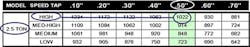
Plot Fan Airflow
With the measured total external static pressure and fan speed setting, you are ready to plot fan airflow on the fan data.
1. Identify the tonnage and fan speed on the fan table.
2. Find the measured total external static pressure on the table.
3. Plot fan airflow by drawing a line between the fan speed setting and the measured total external static pressure.
Plotting fan airflow is an excellent test to include in service agreements or abbreviated diagnostic testing.
As you become better at testing, it becomes an essential step in your diagnostic thought process. When this becomes standard practice, you’ll wonder how you ever serviced equipment without looking at fan airflow.
You will find most residential fans performing at 50% to 70% of required airflow. Below 300 CFM per ton is typical. As an industry, we install new equipment and once started, assume it performs as intended.
The good news is that fan airflow is fairly easy to improve. Simply changing fan speeds or reducing resistance to airflow by installing less restrictive filters or increasing duct system capacity can make a huge difference.
Remember, air is invisible, the easiest way to interpret it is to measure total external static pressure, determine the fan speed setting, and plot fan airflow.
Rob “Doc” Falke serves the industry as president of National Comfort Institute an HVAC-based training company and membership organization. If you're an HVAC contractor or technician interested in a free procedure to measure residential total external static pressure, contact Doc at [email protected] or call him at 800-633-7058. Go to NCI’s website at nationalcomfortinstitute.com for free information, articles, and downloads.
About the Author
Rob 'Doc' Falke
President
Rob “Doc” Falke serves the industry as president of National Comfort Institute an HVAC-based training company and membership organization. If you're an HVAC contractor or technician interested in a building pressure measurement procedure, contact Doc at [email protected] or call him at 800-633-7058. Go to NCI’s website at NationalComfortInstitute.com for free information, articles and downloads.