When testing fan performance, measured total external static pressure (TESP) and fan speed are used to plot airflow on a fan curve. The same principles are used to determine pump flow, measured in gallons per minute (gpm). Let’s take a look at how you can measure pump pressures and plot flow using a pump curve in nine simple steps.
By the way, the test instruments necessary to measure pump pressures include a digital hydro-manometer and accessories or, a pressure gauge attached to the system measuring pressure in PSI.
Dead Head Test Overview
Excluding Grateful Dead followers, the term “Dead Head” describes a test that water balancers use to estimate pump flow. The test is also called a Pump Shut-Off Head Pressure Test.
Both names describe the pump condition during the test. The discharge valve is closed, leaving the pump rotating as it pushes water against a closed valve with no flow through the system.
The “Dead Head” pressure is plotted in feet of head on a curve from the pump manufacturer. This verifies the pump flow potential and impeller size. Without this test, the pump flow or impeller size are unknown. With these two data points known and plotted, you can effectively test, diagnose, and balance with confidence.
Later in the testing process, you can use the knowledge gained from the dead head test to plot pump and system flow under normal operating conditions.
How to Perform a Dead Head Test
Step One –Assure the system is 100% complete and filled with fluid.Any air must be removed from the system. See HotMail article, "Prepare to Balance a Water System."
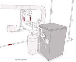
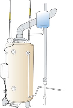
To be able to test pressures, test ports are required in the system before and after the pump to test pump pressure. The test ports allow pressure probes to be inserted into the fluid stream to measure pump pressures.
Some systems are built with a pump gauge bridge consisting of piping and shut off valves near the pump. Test ports or a permanent pressure gauge can be installed in the bridge to measure pressure. The valves can be opened and closed to direct system pressures to the pressure gauge or a hydro-manometer.
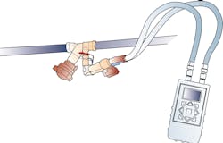
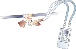
Step Two – Connect a hydro-manometer to the system. Connect test hoses to the meter and the test port insertion probes. Fill and purge all air from thetest hoses, then start and zero the hydro-manometer.
Connect the red hose to the test port located on the discharge or high-side of the pump. Connect the blue hose to the test port located on the suction or low-side of the pump.
Step Three — Start and prepare the system. With the pump operating, slowly close the discharge valve located near the pump outlet. Be certain to leave open the valve before the pump inlet or suction side.
If the system has been previously balanced, mark the valve positions before the test.This allows you to reset the valve to the previous position or system flow, if necessary.
Step Four – Measure and record the pump pressures. With the discharge valve closed, read and record the pump suction and discharge pressures. Pressures near the pump are measured in Pounds per Square Inch (PSI).
If the system has a permanently installed pressure gauge, assure the gauge reads accurately in PSI, then adjust the valves to read pump suction and discharge pressures.
Step Five —To determine pump Dead Head Pressure, subtract pump inlet pressure from discharge pressure. Example: The measured discharge pressure is 31.4 PSI and the measured suction pressure is 18.3 PSI. Subtract the discharge pressure of 31.4 from the suction pressure of 18.3 PSI. This equals a Dead Head pressure of 13.1 PSI.
Step Six — Convert PSI to Feet of Head Pressure.Pressures near the pump are often measured in PSI, however operating system pressures and pump curves use Feet of Head. To convert PSI to Feet of Head, multiply measured PSI times a 2.31 conversion factor. Example: 13.1 PSI times 2.31 equals 30.3 Feet of Head.
Step Seven — Plot the pump impeller size. Using the manufacturer’s pump curve that matches the pump being tested, mark the Feet of Head at zero flow on the left side or axis of the pump curve.
Mark the pump curve using the 30.3 Feet of Head on the left axis. This intersects with the impeller size of 5.63 inches for this pump. Use the 5.63 impeller pump curve line to plot all pump properties for this system.
Step Eight — Test pump pressures with discharge valve open. Open the pump discharge valve and return it to normal operation. Using the hydro-manometer or pump gauge bridge, measure and record the pump discharge and suction pressures again.
Step Nine — Calculate and plot the pump operating pressure.Using the math procedures in steps five and six, calculate the pump operating Feet of Head.
If we assume the pump operating feet of head is 24 feet, draw a horizontal line on the pump curve from the 24 feet until it intersects the downward curved line representing the pump’s performance with a 5.63-inch impeller.
Next, draw a straight line down from that intersecting point until it intersects the gpm line or axis at the bottom of the pump curve.
The pump curve shows pump flow under operating system conditions is approximately 132 gpm.
In many ways, water system testing mirrors air system testing. Some of us are better wetheads and others are better airheads. Hopefully this introductory water balance article will encourage the airheads to seek more knowledge about water balancing. Perhaps wetheads will better see the need to share your knowledge with the airheads. Together, we can constantly improve the performance of the systems we sell, install, and service.
Rob “Doc” Falke serves the industry aspresident of National Comfort Institute, Inc., an HVAC-based training company and membership organization. If you're an HVAC contractor or technician interested in a free test procedure describing simple testing you can do on a sales visit,contact Doc [email protected] call him at 800-633-7058. Go to NCI’s website at nationalcomfortinstitute.com for free information, articles, and downloads.
About the Author
Rob 'Doc' Falke
President
Rob “Doc” Falke serves the industry as president of National Comfort Institute an HVAC-based training company and membership organization. If you're an HVAC contractor or technician interested in a building pressure measurement procedure, contact Doc at [email protected] or call him at 800-633-7058. Go to NCI’s website at NationalComfortInstitute.com for free information, articles and downloads.


